
Experts in air filtration
Project HAD – Lean Phase Conveying System for Lime APCR in Wales
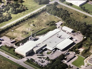
The enquiry for the lean phase conveying system was to remove the operator involvement in handling hazardous waste from the existing flue gas treatment plant.
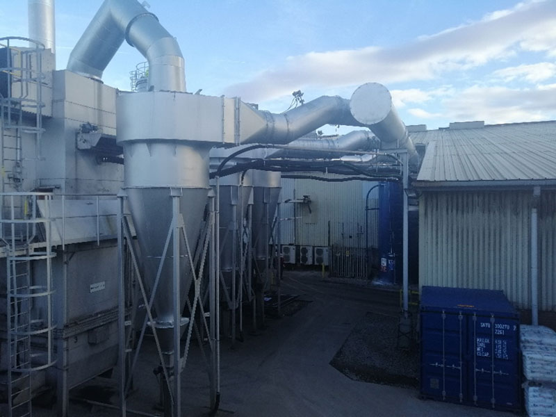
The existing filter system was split into three bag filters each with a cyclone. Each cyclone and filter have a rotary valve which was discharging into a bulk bag. Rather than collect the spent lime and aluminium dust into bulk bags we proposed a lean phase conveying method into a silo. This would replace the bulk bag collection method and remove the need to handle the hazardous waste and also make collection cheaper and easier via a tanker.
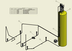
Our scope was broadly:
- 65cu Silo with inclined screw and bellows discharge system.
- Exhauster
- Filter Separator / Vent Filter
- Stainless steel pipe work with EPDM rubber bends
- Controls System
- Installation including removal and erection of three new ‘’free issue’’ cyclones Chimney, as a contract addition
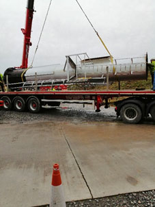
The lean phase system was to be installed to coincide with the plants 6-week shutdown. This meant the project needed to be planned with military precision around the Filter Designs workforce and other external contractors, to ensure that the lean phase conveying system was installed and commissioned within five weeks.
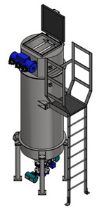
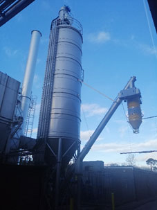
65cu Silo
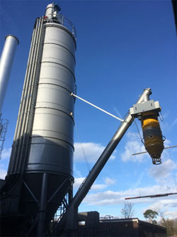
The 65cu silo is a fully welded silo with an access ladder and two rest platforms. The silo is fully welded and the RAL colour was specified by our client.
The silo has a capacity of 33t at a bulk density of 512kg/m3, which gives us headroom on the 26t a standard tanker can collect at one time.
The silo has a high-level probe on the top with an extension to avoid overfilling and also a mechanical over pressure relief valve.
It has an anti-slip pedestrian roof along with an access manhole handrailing and kickplate.
Just above the discharge there is a 3kW agitator (in house design) to break up the lime / dust prior to discharge.
As the process produces minimal dust (around 7kgs/hr per filter / cyclone discharge), the dust can be sat in the silo for up to 6 weeks before the discharge is used.
Below the agitator is an aeration system with 8 nozzles which are in use when the butterfly valves are opened on the discharge sequence.
The discharge system at the base of the silo is multi-functional.
A butterfly valve sits above an inclined screw and opens when the discharge sequence is called for. The 18kW screw is inverter driven to allow different speed settings for the discharge as there are two options.

The first option is to discharge to the tanker via the bellows. The bellows system has its own built in fan (for dust extraction) which is then fed back into the tanker, it also has a built-in air filter with a pulse cleaning tank.
The bellows are lowered into position using the pendant and has two proximity switches, one at the top and one at the bottom. Once the tanker is in place the operative presses the down arrow on the pendant (which switches the proximity switch and starts the dust extraction and pulsing) Once the pendant has been lowered all the way (passed the second switch) The system will delay for XXa set time then discharge into the tanker. On the bellows discharge there is a paddle level probe which indicates when the tanker access is full and to move onto the next access hatch.
The second discharge is via a manual slide valve which can discharge into bulk bags. Our client wanted to have a second discharge option in case there was ever a problem getting a tanker to site. The manual slide valve also has proximity switches fed back to the PLC which shows the status of the valve.
Also as a fail safe third option we incorporated a 4’’ uni-cone coupling with a manual bray valve so the silo can be emptied via suction from the tanker If the need should ever arise.
On each silo leg we have load cells which monitor the overall weight in the silo.
The load cells also work as a weight check over 24 hours for each bag filter so the operatives know if one bag filter is being starved of lime as there isn’t a dosing rate monitor present on the lime injection system currently.
Exhauster
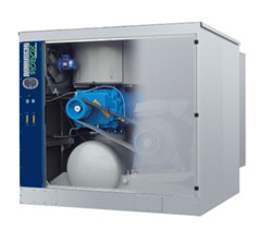
The exhauster was designed to convey 33kg/hr of lime with a bulk density of 510kg/m3 under vacuum conditions through a 65mm diameter line of a maximum 75.5m overall length with an included vertical lift of 17m allowing for 9 off 90° bends and one 45° bend.
We needed to size the exhauster before designing the filter separator.
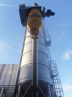
Filter Separator / Venting Filter
The filter separator was designed in house using inventor 2019. Using the maximum volume from the exhauster we needed 9 bags to give us a filtration area of 5.51m2.
The filter separator was made cylindrical to minimise the footprint as this needed to be located on top of the silo and also needed to be strong due to the negative pressure of the exhauster.
The filter separator has three inlets each with an actuated ball valve which was linked to the three filters / cyclones so only one pipe run was conveying at one time.
The filter separator has its own pulse cleaning system to clean the bags which includes a pulse controller, 3-way pulse tank which clean on differential pressure.
In the side of the filter, we installed a capacitance level probe to monitor the dust levels. The discharge is via two butterfly valves which work on a timer basis and constantly discharge into the silo to avoid any dust being kept in the filter separator.
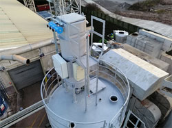
Due to the height of the filter separator we couldn’t place a safety cage due to height restrictions so we opted for a glide loc safety system to ensure the safety of the operatives when servicing or changing the filter bags.
Due to the displaced air coming into the silowe need to vent this to atmosphere. wWe have an in-house standard design for a vent pulse filter which is a single cartridge which is mounted in a housing which also pulse cleans the cartridge when discharging to the silo which is controlled via a 24vdc solenoid.
Stainless steel pipework with EPDM rubber bends
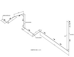
To be able to size the exhauster we first needed to produce a line diagram showing the worse pipe run out of the three. We then sent this to our exhauster supplier to get the correct volume and what bore size the pipe needed to be, to allow the correct volume and velocity throughout.
Once the pipe had been correctly sized (2.5’’) we chose to use a standard schedule pipe in stainless steel to minimise the fabrication time.
Due to the waste dust having lime in it we opted to have the conveying lines bring warm air from the furnace building to keep the pipe lines warm in winter periods and also reduce moisture.
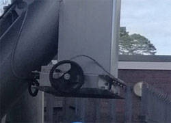
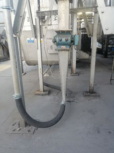
Each pipe run was connected with morris couplings and jubilee super clamps for the bends. We used EPDM rubber for the bends to allow easy removal and also more flexibility when installing on site.
The pipe work was supported with pipe clamps and specially made support brackets.
Each pipe run was connected with morris couplings and jubilee super clamps for the bends. We used EPDM rubber for the bends to allow easy removal and also more flexibility when installing on site.
The pipe work was supported with pipe clamps and specially made support brackets.
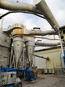
Chimney
After we had been awarded the project our client decided to replace one of the existing chimneys to future proof the system further.
We were able to have the old chimney removed and the new one installed within four weeks, even removing the old chimney from site for the client.
The new chimney was manufactured out of 8mm thick mild steel and needed to conform to M1 sampling requirements for stack emission monitoring.
We designed the new chimney to be able to use the same fixing ring as the previous chimney and after some civils calculation we were able to resin anchor fix some new bolts too.
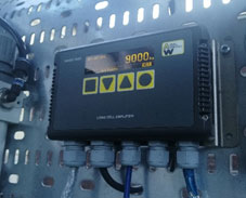
Controls System
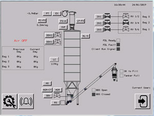
Our client specified an Allen Bradley logix plc to be able to communicate to the SCADA.
We produced a functional design specification, P&ID’s and also a basic electrical list for our controls specialists to produce the controls programme.
We try to make all of our HMI controls screens as easy to use as possible to help out the operative’s with basic usage and also fault finding.
As the six rotary valves were being controlled via our clients control panel we needed to have both our of panels intercommunicating so each inlet valve on the filter separator coincided with each paired rotary valve as well as the load cell check weights.
The installation needed to coincide with the plants six-week shutdown. As well as installing a lean phase conveying system and replacing the chimney, the plant also required three new cyclones which had been pre-ordered via another supplier.
Part of this project was to undertake the removal and installation of these cyclones. This meant needed to prepare an installation plan and Gannt chart to ensure that these sites activities didn’t clash with our own.
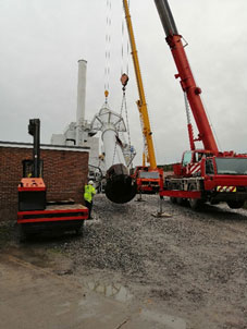
To minimise site disruption we utilised contract lifts from the same crane specialist as the client was using elsewhere on site which ensured all parties were aware of the schedule and able to maximise the use of the crane.
Although the schedule was very tight we successfully managed to finish the installation on time, which allowed us a week to commission the plant.
All three new cyclones all fitted.
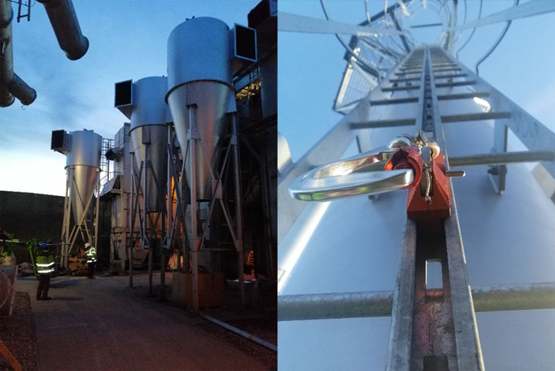
Cyclones prior to original ducting going back in. - Glide loc system installed on the chimney
Our recent Projects
We were contracted to provide 2 small Ceramic filters suitable for a small volume but with a design maximum temperature of 600°C. In addition the filters will be handling a syngas which cannot be mixed with oxygen so an alternative to compressed air would need to be used for the ‘Cleanpulse’ cleaning of the 25 Ceramic element in each of these CPC78 filters. In addition dosing of small amounts of a re-agent is required so the client also opted for a ‘Cleandose’ 25kg bag skid. Find out more about Project CAD below.
Project SRCL HH - GSA (Gas Suspension Absorber) Reactor Tower
Project BCI - Bag Filter, Gas Suspension Absorber, Reagent Dosing for a Challenging Carbon Process
Filter Designs Ltd. 2020 - Website by 1PCS

