
Experts in air filtration
Project FT – Dust Extraction to Wet Cyclone on Brick Manufacturing Plant. World First Brick Cleaning System
FDL had been contacted to look at the existing dust extraction system back in 2014 as the dust in air levels were high and some form of remedial action was required.
Initially FDL were contracted on a consultancy basis to assess the existing system and provide detailed reports, specifications, designs and drawings to allow Forterra to go out for quotation for a new ducting system.
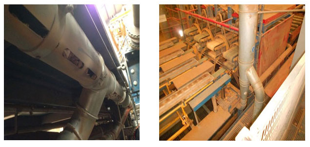
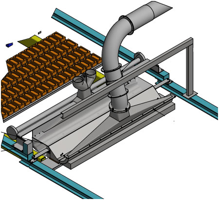
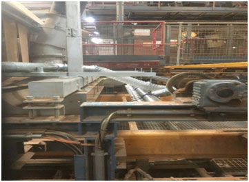
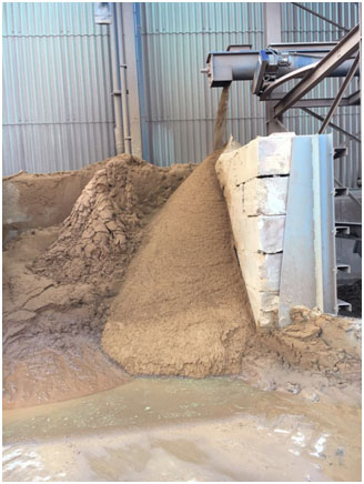
FDL was then appointed as the main contractor to provide a turnkey solution to the problem. The main scope of this project was to replace much of the existing ducting which was found to be extensively blocked owing to the hoods being underneath the conveying systems (Image 1) With the bricks warm the airborne dust rising, the dust wasn’t being captured which was causing the high dust levels in the workplace (image 2)
Image 1. Blockages in existing ducting - Image 2. High dust levels in the workplace
The main wet cyclone which fed the ducting was to be reused as this was deigned to be able to handle 96,000m3/hr. Through our consultancy we were able to design a system using newly placed hoods over the area’s most prone to dust.
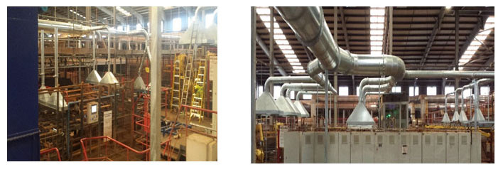
The ducting design was extensive and spanned a large part of the automated plant this included 44 newly designed hoods varying in size and volume (Images 3 + 4) all hoods were manufactured from 2mm galvanised steel. Each branch of ducting had a blast gate damper fitted to be able to balance the system once installed. Most hoods had durable plastic curtaining to assist with the capture of the airborne dust.
Image3. Ducting + hoods - Image 4. Ducting + hoods
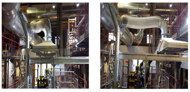
The largest hood needed to be fully retractable so the maintenance team could change a specific turning belt which needs to be changed eight times a year. This was done by placing the hood on castor wheels running backwards and forwards in a ‘u’ shaped channel. A large section of channel on either side was made removable using quick release pins and tailgate latches to secure the desired position. PU flexible ducting is used to connect the hood to the main branch of ducting (Images 5 + 6)
Image 5. Hood retracted, beams still in place - Image 6. Hood in extracting position
The second part of this project was to remove dust from the ‘Frog’ of the brick. The bricks pass along a conveyor on 4 metal grates each grate having 22 bricks on each. The aim was to remove and collect the dust / sand from the frog.
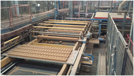
The only place we had the opportunity to place the ‘’frogging’’ hood was after the bricks came from the kiln.
Having the 88 bricks pass under the hood at a rate of 1 second we knew this was giong to be a challenge.
Orginally we designed a hood with 3 sections. The middle section was for suction and the outer sections were for blowing the dust out of the frog. Using a fan on the filter for suction and 2 blowing fans either side of the coveyor.
The idea was to agitate the dust from the frog and have the suction fan extract dust to the filter. Whilst the hood was collecting some of the dust this wasn’t enough to clear the frog.
We set up a small test rig in our workshop to see if sperating the hoods to try and blow off the dust as it passed through into a suction hood, before designing hoods to do this.
Redesigning to split the hood into two. 1 hood for suction and 1 for blowing, was proven to work on a small scale.
One the system was installed we found that we were removing 80% of the frog dust / sand, altough this was a massive inprovement on the last blowing hood we wanted to be able to clear all of the frog for our client to:
- Reduce the costs of buying in sand
- Reduce the dust / sand being moved around site and causing wear and a dusty enviroment.
Our client was also keen to remove as much dust from the frog as possible.
To do this we collaborated with our client to set up a DOE (Design of Experiment) test to determine the best set up to optimise the collection. This was done using a program called MINITAB, this allows you to put in various parameters, in this case these were height from the brick, distance from the suction hood and the angle of the blower.
Once the various test were completed we found the optimum setting and placed the blower. We then ran a trial which meant weighing a sample of bricks to determine how much dust / sand was in the frog. We disconneted the entrainment hopper and placed a bulk bag on the bottom of the filter to capture the snad / dust collected.
We let the test run over a few hours and found that we were removing 107% of the brick dust. Not only was the blower removing the frog dust but also scrubbing the brick hence the extra 7%.
To date this is the only multiple frog cleaner in the world. There are other frog cleaners but these work on a single brick at a time.
The CPC25 - Cleanpulse Cartridge Filter (image 8) uses a HARDOX inlet baffle section and a drop out chamber designed to protect the cartridges from the coarse brick dust collected. Hydraulic gas struts were used to make the top access hatch convenient and safe to use. A single case mounted centrifugal fan is used to provide the dust extraction at the Frog hopper.
The third part of the project was the vacuum system and discharge. The client required a centralised vacuum system that they could clean the plant with easily during shutdowns giving not only a cleaner workplace but also as a preventative maintenance measure. They had previously been using hired in vacuum skips.
The vacuum system incorporates fifteen different hose points situated around the plant in locations identified by the client. This gave good site coverage but meant the hoses weren’t overly long or heavy during operation
The system utilises a 22kW exhauster (image 9), entrainment hopper and a filter separator (image 10). The vacuum system is split into two lines. The first line conveys the dust collected from the Frog, via the entrainment hopper underneath the CPC filter to the filter separator located on top of our Dust Storage Hopper outside (fig11). The second line conveys the dust collected when cleaning the plant via the hose connection points.
Image 9. 22kW exhauster - Image 10. Entrainment hopper
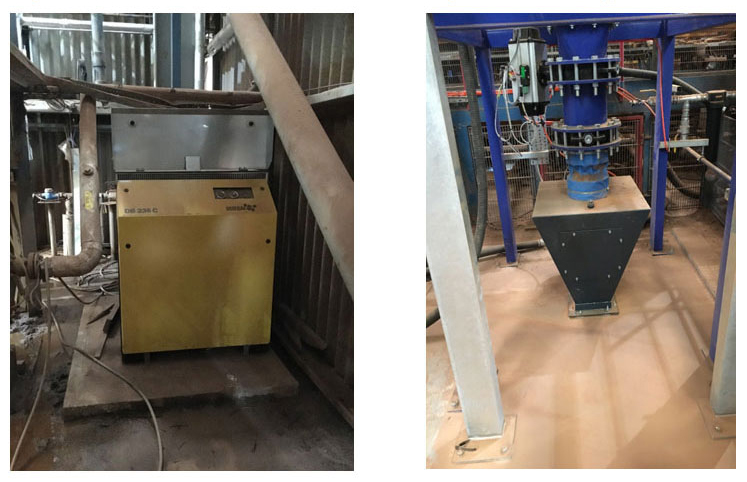
Image 11. Filter separator - Image 12. Wet deduster on slewing ring - waste skip
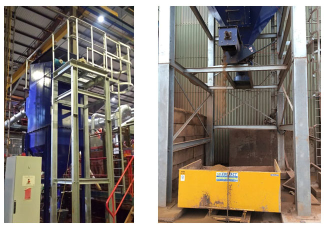
Image 12. Wet deduster on slewing ring – recycling bund
Our recent Projects
We were contracted to provide 2 small Ceramic filters suitable for a small volume but with a design maximum temperature of 600°C. In addition the filters will be handling a syngas which cannot be mixed with oxygen so an alternative to compressed air would need to be used for the ‘Cleanpulse’ cleaning of the 25 Ceramic element in each of these CPC78 filters. In addition dosing of small amounts of a re-agent is required so the client also opted for a ‘Cleandose’ 25kg bag skid. Find out more about Project CAD below.
Project EE - CleanNOx SNCR System
Project JP2 - Complete Flue Gas Treatment System for Intumescent Paint Furnaces (Phase 2)
Filter Designs is a trading name of Turnkey Filtration Limited, a limited liability company registered
in England under number 16279255, whose registered office is at Filtration House, Farndon Road, Market Harborough,
LE16 9NP - Website by 1PCS

